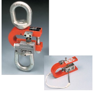
DynaSwitch for cable ends and supported loads. (pictured with options)
Note: We offer discounts on all Dillon products. For a best price call 800-572-2531 or click on the link to email us at sales@johnsonscale.com
Dillon DynaSwitch systems are reliable, low cost way to control forces and prevent overloads. They can be used in automation controls, acting as scales. They can be used on cranes, hoists and elevators-not only to shut off power when an overload condition exists, but they can also be set to operate lights, buzzers or klaxons to warn of an impending overload. Like 24 hour sentinels, they can operate in normal or extreme environments. The heart of a system is a force beam which operates in tension or compression. Seven different load capacities are available. Switch and physical connection options are listed. Each beam can accomodate from one to four switches which can then be set to operate as many as four different switching functions or combinations including slackline detection.
All DynaSwitch force beams and attachment fittings have an ultimate safety factor of 5:1 (4:5-1) for metric capacities. In addition, all models have an overload stop or bolt to provide extra protection to the measuring ability of the DynaSwitch force beam. Switches can be set to trigger at the loads you desire, if specified at the time of order.
Dynaswitch Options
Option A Low Differential travel switch for use on DSW1-DSW-2,and DSW-4 only. For use in controlled environment. Single Pole, double throw. 5 amps at 125 or 250 VAC, 12″ leads included.
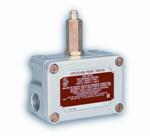
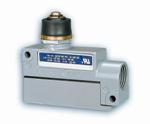
Option B Weatherproof low differential travel switch for use on DSW-3,DSW-5,DSW-6, DSW-7 and Craneguard. Has neoprene gasket around housing halves for tight seal. Includes elastomer seal boot around the actuator. Sealed conduit connectors. Die case aluminum housing meets NEMA1 and NEMA4 enclosures. Single pole, double throw, 0.002″ travel. 15 amps, 125,250 or 480VAC.
Option C explosion proof switch for use on DSW-3,DSW-5,DSW-6,DSW-7 and Craneguard. For use in hazardous locations (Class I,Div, 1, groups E,F & G). Flame paths within the housing cool expanding gases below kindling temperature before they reach the explosive gases surrounding the housing. Single pole, double throw. Aluminum enclosure.(not sealed against liquid) 20 amps, 125, 250, 0r 480 VAC
Option J Weatherproof low differential travel switch for use on DSW-1,DSW-2 and DSW-4 only. Sealed for use in high environment situations. Single Pole, double throw. 5 amps at 125 and 250 VAC, 12″ leads included.
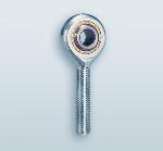
Option D rod end connectors for tension rigging. Self aligning rod end connectors are normally mounted at right angles to each other providing universal alignment under load. They can be mounted parallel to the force beam upon request.
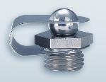
Option E for all capacities. Hardened ball and cup with retaining clip for compression use. Heat treated alloy steel. Cup is highly polished and plated. Ball is held in place by spring clip held by shoulder of cup. Slightly different configuration for higher ranges.
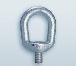
Option F Lifting eye for tension use. Hardened steel threads into force beam. Oriented parallel to the force beam unless otherwise specified.
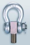
Option G adapter, shackle and pin. A hardened forged steel shackle with adapter and pin for tension rigging of Dynaswitches. Shackles and similiar fittings are installed at time of manufacturer with the plane of the top fitting lifting parallel to the be beam length and 90 degree to the position of the bottom fitting.
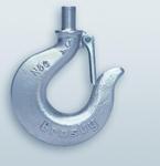
Option H Non swiveling Hook- A hardened forged steel hook threaded to fit the 2000lb and 10000lb load switches only. Has spring latch. Should be installed at time of manufacture before setpoints are adjusted
Option S threaded stud for applications where conventional shackles or attachment eye cannot be used. Will accomodate yokes and other special fixtures. Heat treated alloy steel.
Options are not available separately; only as part of a complete assembly.
How to order:
- Specify model number
- Specify switch option and quantity
- Specify fitting option desired on top of force beam
- Specify fitting option desired on bottom of force beam
- Specify switch setpoint(s) and direction if factory setting is required (contact us prior to ordering)